The following is a procedure developed by Dr. Ping Chen of the Materials Science Department at the University of Southern California for the use of this kit in a University laboratory. We thank Dr. Chen for allowing us to publish his procedure here:
Introduction:
Superconductors are materials the electrical resistance of which drops to zero when cooled below a certain temperature, the so-called CRITICAL TEMPERATURE (Tc). The synthesis of high Tc superconductors in 1986 allows attaining superconductivity even in the classroom without the use of complex cryogenic equipment. In this experiment, we will use liquid nitrogen to cool a high Tc superconductor, YTTRIUM-BARIUM-COPPER-OXIDE (YBCO), to 77°K and observe its resistance transition.

Note: In the model 500 kit, the superconducting ring shown in Fig. 1 is replaced by a superconducting bar.
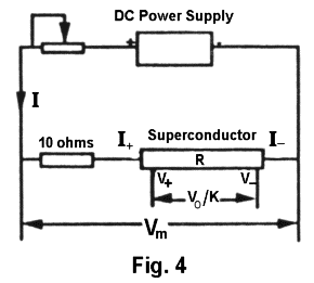
The resistance of a conductor can be determined by measuring the current passing through the conductor and the voltage drop developed across the conductor by the passing current. Since, even at room temperature, the resistance of the YBCO bar used in the experiment is very low and comparable to the resistance of the connecting wires, a special method must be used to measure its resistance. The circuit used in the experiment is shown in Fig. 1 above. A bar made of YBCO is connected in series with a CURRENT ADJUSTMENT potentiometer and a current monitor resistor (10-ohms) in a DC circuit. The current passes through the bar via the terminals I+ and I-. The current is adjusted by varying the potentiometer and monitored by measuring the voltage drop Vm (CURRENT MONITOR voltage) developed across the current monitor resistance (10-ohms) and the bar. Since the resistance of the YBCO right is extremely small compared to the current monitor resistance (10-ohms), the current passing through the YBCO bar I is approximately equal to Vm/10. The voltage drop developed across the two terminals V+ and V- of the bar is amplified using a high input impedance amplifier with a preset gain of K=100. The amplified VOLTAGE OUTPUT Vo is measured using a voltage meter. Then the resistance R of the bar can be determined from the formula R = Vo/(KI). This way of measuring the resistance is generally called the four probe measurement. Note that the two terminals (probes), I+ and I-, for the current path are separated from the two terminals (probes), V+ and V-, for the voltage measurement. Since there is no current passing through the voltage measurement loop and the input impedance of the voltage amplifier is very high, the measurement error which could have been induced by the resistance of the connecting wires is eliminated.
The temperature of the superconductor is monitored by a diode sensor. A diode thermometer circuit converts the signal to a calibrated TEMPERATURE MONITOR voltage (1 millivolt corresponds to 1°K).
Equipment and Supplies
Superconductor Probe Board
Electronics Board
Two multimeters
DC power supply
Styrofoam cup for liquid nitrogen
Plastic cap
Wire connectors, screwdriver
Liquid nitrogen
Procedure
1. Get familiar with the instruments:
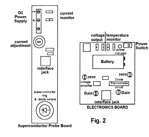
The whole circuit for measuring the resistance of the superconductor is mounted on two separated boards: The SUPERCONDUCTOR PROBE BOARD and THE ELECTRONIC BOARD (Fig. 2). The boards are interconnected through the INTERFACE JACK.
- Caution: This experiment uses delicate electronic circuitry and superconducting material. You must observe strictly the following instruction to avoid damage to the set-up.
THE SUPERCONDUCTOR PROBE BOARD. At one end (bottom) of the probe a bar-shaped YBCO is mounted on a brass or aluminum disk. This end is intended for immersion in liquid nitrogen. A silicon diode is imbedded in the disk for sensing the temperature of the bar assembly. The other end (top) of the board, operated at room temperature, holds the component for electrical hook-up and the resistor network for current adjustment and monitoring.
- Caution: Avoid thermally shocking the materials. Follow exactly the instructions for cooling down the superconductor probe. A wet probe should never be immersed in liquid nitrogen because of the possibility of destructive ice expansion between components. Water can easily condense on the cold end of the probe. Follow exactly the instruction for preventing this condensation.
THE ELECTRONICS BOARD consists of the high impedance voltage amplifier and the diode thermometer circuit. The locations of the electrical hook-up are shown in the figure. In addition, there are four adjustment potentiometers on this board. In this experiment, you might need to adjust the ZERO of the voltage amplifier and the GAIN of the diode thermometer circuit.
Caution: Do not touch the other two adjustment potentiometers. They have been preset to assure the gain of 100 of the voltage amplifier and the calibrated temperature monitor voltage offset.

Note: In the model 500 kit, the superconducting ring shown in Fig. 2 is replaced by a superconducting bar.
The "–" terminals of the outputs (green connectors on the electronics board) are connected together to the common of the electronic circuit. A 9-volt battery feeds the electronic circuit board. When that power is turned on, a POWER INDICATOR blinks, indicating that the battery is supplying power.
2. Make the electrical connection of the instruments.
(2.1) connect the terminals, DC POWER SUPPLY "+" and "–" on the SUPERCONDUCTOR PROBE BOARD, to "A+" and "A-" leads of the DC power supply, respectively. Make sure that the power switch of the DC power supply is at the "OFF" position. Set the knobs and switches on the front panel of the DC power supply as follows: METERING switch: "A AMPS" position; MODE switch: "INDEPENDENT"; VOLTAGE ADJUST KNOBS (A and B): fully counter-clockwise (minimum).
(2.2) Connect the ELECTRONIC BOARD and the SUPERCONDUCTOR PROBE BOARD through the interface jack, using the provided telephone jack connector.
(2.3) Connect the terminals VOLTAGE OUTPUT "+" and "–" on the ELECTRONIC BOARD to the "+" and "–" leads of a multimeter, respectively. Set the multimeter to the "DC V" range. This multimeter is referred to as the VOLTAGE METER later.
(2.4) Connect the terminals TEMPERATURE MONITOR "+" and "–" on the ELECTRONIC BOARD to the "+" and "–" lead of the other multimeter, respectively. Set the multimeter to the "DC V" range. This multimeter is referred to as the TEMPERATURE METER later.
(2.5) Turn on the multimeters. Both should show a zero reading.
(2.6) Ask the TA to check the circuit connection. After getting the TA's permission, go to the next step.
3. Make the initial check of the ELECTRONIC BOARD.
(3.1) Turn the POWER SWITCH of the ELECTRONIC BOARD to the ON position (right end). The power indicator starts blinking.
(3.2) Write down the reading of the TEMPERATURE METER. One millivolt corresponds to 1°K. The room temperature measurement might not be very accurate using this diode sensor. However, this is not important for the experiment since we will concentrate on the low temperature measurement.
(3.3) Adjust the ZERO potentiometer of the VOLTAGE AMPLIFIER on the ELECTRONIC BOARD, using a small screwdriver, to make the reading of the VOLTAGE METER zero.
4. Adjust current passing through the superconducting bar.
(4.1) Pull the "+" lead of the VOLTAGE METER out of the "+" terminal of the VOLTAGE OUTPUT on the ELECTRONIC BOARD. Plug it into the CURRENT MONITOR "+" terminal on the SUPERCONDUCTOR PROBE BOARD.
(4.2) Double check that the "VOLTAGE ADJUST" knob on the front panel of the DC power supply is fully counter-clockwise (minimum voltage output) and the power switch of the power supply is in the OFF position.
(4.3) Ask the TA to check your settings. Under the TA's supervision, insert the plug of the DC power supply into the wall outlet and then turn on the power switch of the DC power supply.
(4.4) Slowly increase the voltage of the DC power supply, by turning the "VOLTAGE ADJUST" knob clockwise. Monitor the reading of the VOLTAGE METER. Adjust the DC power supply to get a reading of the VOLTAGE METER Vm = 1 volt. This corresponds to a current of 100 ma. passing through the YBCO bar (I = Vm/10). The current can alternatively be adjusted by adjusting the CURRENT ADJUSTMENT potentiometer on the SUPERCONDUCTOR PROBE BOARD. If necessary, the TA will help you to re-adjust that potentiometer.
5. Measure the room temperature resistance:
Put the "+" lead of the VOLTAGE METER back to the "+" terminal of the VOLTAGE OUTPUT on the ELECTRONIC BOARD. Measure the amplified voltage drop developed across the YBCO bar (amplification gain is normally preset at 100). Knowing the voltage drop and the passing current, you can calculate the resistance of the YBCO bar at room temperature. Write down your result.
6. Double check the "zero" output of the VOLTAGE OUTPUT by turning off the DC power supply. (Caution: MAKE SURE that the VOLTAGE ADJUST is not touched when doing so.) If the zero output is shifted from zero, you can re-adjust the ZERO potentiometer of the VOLTAGE AMPLIFIER on the ELECTRONIC BOARD.

7. Cool the superconductor and measure the change of its resistance.
(7.1) The TA will help you get liquid nitrogen into the styrofoam container. The container should be half filled.
- Caution: Liquid nitrogen is at 77°K. It is considered a hazardous substance. If mishandled, it can cause frostbite or eye damage. Handle the styrofoam container carefully. Move it on the table slowly. Never shake it. Keep your face at least one foot away from the container. The frost condensing on the outside of the container is normal. Do not panic if a drop of liquid nitrogen falls on your body. It evaporates rapidly and you will feel nothing when the amount is small. If accidently a lot of liquid nitrogen spills on your clothes, immediately separate the "wet" part from your body. Wait until it becomes "dry." It usually takes less than a minute for this to happen. As long as you are careful during the operation, you should not have any problems.
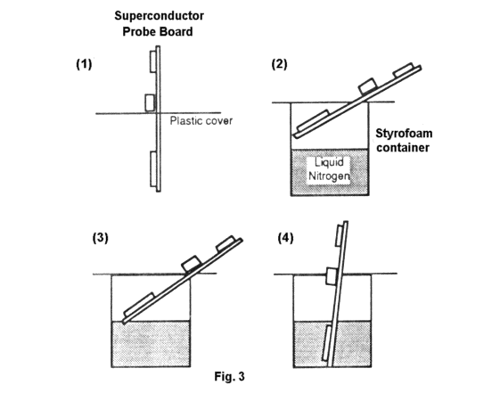
(7.2) Insert the SUPERCONDUCTOR PROBE BOARD into the slit of the provided plastic cap. Let the plastic cap be below the interface jack, as shown in (1) of Fig. 3.
(7.3) Insert the SUPERCONDUCTOR PROBE BOARD into the liquid nitrogen container in such a way that the bar assembly is kept above the liquid level and the plastic cap covers the opening of the container, as show in (2) of Fig. 3. The bar assembly is gradually cooled by the cold nitrogen evaporating from the liquid nitrogen. The plastic cap prevents the air from entering the container to form frost on the superconductor bar being cooled down.
- Caution: NEVER insert the probe straight from room temperature into the liquid nitrogen. It will break the superconductor bar. Keep the plastic cap as close as possible to the opening of the container in order to prevent the water condensation on the bar assembly.
(7.4) While performing step (7.3), one person should monitor the reading of the TEMPERATURE METER. If the temperature drops too fast, lift the probe a little.
(7.5) Measure the VOLTAGE OUTPUT Vo in steps of 10°K of temperature change.
(7.6) When the temperature drop becomes very slow, slightly insert the probe a little more. You can wipe frost condensed on the plastic cap and see the end of the probe. Meanwhile, listen carefully. If you hear a hissing noise, the end of the probe is touching the liquid nitrogen. Just lift the probe a little from that position. Continue measuring the resistance change.
(7.7) The probe can be cooled to about 120° K by the cold nitrogen gas evaporating from the liquid nitrogen. From that point, you should insert further the probe until you hear the hissing noise. Now use the liquid nitrogen in contact with the end of the brass or aluminum disk to cool down the whole bar, as shown in (3) of Fig. 3. You will notice that the temperature drops again and the VOLTAGE OUTPUT drops rapidly, indicating that the superconductor is cooled below its critical temperature and becomes superconducting. The data of the change of the VOLTAGE OUTPUT vs. the TEMPERATURE MONITOR in this stage is not reliable since the bar assembly is not cooled uniformly. We will measure the superconducting transition more accurately in the next step.
8. Measure the superconducting transition near the critical temperature.
(8.1) You can immerse the bar assembly completely into liquid nitrogen when the TEMPERATURE MONITOR is about 80°K, as shown in (4) of Fig. 3.
(8.2) After the bar assembly has been immersed into liquid nitrogen for one minute, the TEMPERATURE MONITOR reading should be 77 millivolts (77°K). If not, adjust the GAIN potentiometer of the diode thermometer on the ELECTRONIC BOARD to make the reading 77 millivolts.
(8.3) You might notice that the VOLTAGE OUTPUT is not exactly zero when the YCBO bar is in the superconducting phase. Instead, it increases to several millivolts when the whole bar assembly is immersed into liquid nitrogen. Turn off the DC power supply. You will find that the VOLTAGE OUTPUT is no longer zero. DO NOT re-adjust the ZERO of the voltage amplifier on the ELECTRONIC BOARD since this non-zero reading of the VOLTAGE METER is not due to zero-shift of the amplifier. It is related to the thermo-electrical effect and the persistent current effect which will not be discussed in the current experiment.
(8.4) Lift the probe to leave the bar assembly just above the liquid nitrogen. The temperature of the bar increases slowly. Measure the VOLTAGE OUTPUT in steps of 1°K of temperature increase. You will observe a very rapid increase of VOLTAGE OUTPUT when the temperature is near the critical temperature. Try to measure the VOLTAGE OUTPUT in steps of 0.5°K near the critical temperature. Stop the measurement when the temperature rises to 120°K.
(8.5) Check the measured data. If you are unsatisfied with the data, put the bar assembly back into the liquid nitrogen. Let it cool back to 77°K. Then repeat step (8.4). This can be repeated several times provided no obvious water condensation occurs on the superconductor bar assembly. (The plastic cap must be kept so the container is well-covered.) Ask the TA to check if you have enough liquid nitrogen in the container. The TA will help you to add liquid nitrogen if necessary.
(8.6) After collecting the data near the critical temperature, let the bar assembly be warmed up. The plastic cap must be left covering the container during the warm-up. Measure the VOLTAGE OUTPUT in steps of 10°K until the temperature reaches about 210°K.
9. Terminate the measurement.
(9.1) Leave the probe in the container, with the plastic cap covering the opening. The probe will be warmed up to room temperature.
(9.2) Turn off the POWER SWITCH of the ELECTRONIC BOARD. The POWER INDICATOR stops blinking. Rotate the "VOLTAGE ADJUST" knob on the front of the DC power supply to the fully counter-clockwise position (minimum voltage). Turn off the DC power supply. Unplug the DC power supply. Turn off the multimeters. Disconnect the electrical connections.
10. DATA TREATMENT: Everyone should do this part independently.
(10.1) Get a copy of the original data. Have it signed by the TA. The following work is to be done after the class.
(10.2) Create a table of original data, showing the change of the VOLTAGE OUTPUT vs. TEMPERATURE.
(10.3) Calculate the resistance of the superconductor from the original data of the VOLTAGE OUTPUT and the passing current.
(10.4) Create a table showing the change of the resistance vs. the temperature.
(10.5) Plot the change of resistance vs. the temperature on a graph paper. Generally a logarithm axis should be used in the plot when the data variation covers more than two orders of magnitude. So a semi-log graph paper should be used for this plot. The horizontal linear axis is used for the temperature and the vertical log axis is used for the resistance.
Question:
It has been mentioned in the introduction that the current passing through the YBCO bar can be approximately determined by I=Vm/10 since the resistance of the bar is extremely small compared to the current monitor resistance (10 ohms). This statement needs to be further justified. The circuit diagram is re-drawn in Fig. 4. in a simplified form. Having known Vm and Vo/K, find the exact expression of I and R. Compare these expressions with the approximate one used in the experiment, I=Vm/10 and R=10*Vo/(K*Vm). See how much error is introduced when using the approximate expressions.
